 What's New?
 Introduction
 Getting Started
 Magnet Subgroup Calendar
 Library

[ English | Japnese ]
 What's New?
 Introduction
 Getting Started
 Magnet Subgroup Calendar
 Library
 What's New?
 Introduction
 General Characteristics
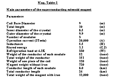
The bore diameter is 9 m and the overall length is 10 m. We divide the magnet into three parts in order to simplify the assembly procedure and also provide a rigid support for the electromagnetic and hadron calorimeters. The supports are taken through the gaps between each coil.

The coil length of each part is 2.5 m and is equipped with its own separate cryostat.
 Parameters of the superconductiong solenoid
The central part and both of the end parts consist of 257
and 278 turns of coaxial coil windings with double layers. This
configuration is to compensate the field drop along the beam axis. The
superconducting magnet requires a relatively thick iron yoke to ensure the
2 Tesla uniform field in the central tracking region. In order to keep
the maximum field in the iron yoke below 2 Tesla, we need a total amount
of 11,500 tons of iron. The overall inductance of the magnet is 5.5
H. Consequently, the total stored energy is 1.1 GJ when the magnet is
operated at 20 kA to produce the 2 Tesla central field.
One of the most important issues in the design of the superconducting coil
is the method of cooling. For the JLC detector magnet, a direct
cooling system is applied with the flow of two-phase helium through a
cooling path in the conductor. In this case, it is very important to
reduce the pressure drop since the cooling path is very long. Three
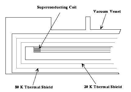
modules are cooled in parallel. Also, in our design, two shields cover
the coil at 20 K and 80 K. The 20 K shield is essential to reduce the
helium amount further by controlling the pressure drop to be less than 0.2
kg/cm2.

The cryostat is a vacuum chamber with superinsulation. Two shields at 20 K and 80 K are cooled by the helium gas flow from the refrigerator. The heat flow to each coil is 4 W/coil, resulting in 12 W in total. This corresponds to a liquid helium flow of 6 g/sec. It is expected to take a long time for initial cooldown since the path is very long. To reduce the cooldown time, we are considering extra cooling channels on the outer cylinder of the coil. The total heat load for this magnet at 4.2 K is estimated to be about 330 W. Therefore, a medium class refrigerator with a cooling power of 500 W (corresponding to electric power consumption of 500 kW) is enough to operate the magnet.
Conductor

 Parameters of the superconductiong solenoid
The operation current and maximum
temperature are 20 kA and 5.0 K, assuming that the helium pressure at the
inlet is 0.3 kg/cm2 and the local temperature rise is 0.5 K. On the other
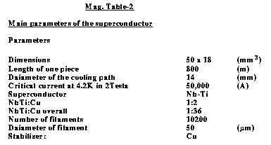
hand, the critical current of the conductor is 40 kA at 5.0 K in a 3 Tesla
field (50 kA at 4.2 K in the same field).
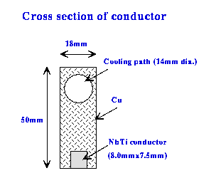
The coil is made of NbTi/Cu
multifilamentary superconducting cables. The cable consists of 10200
filaments with 50Ám in diameter. The NbTi/Cu ratio is chosen to be 1/2
for easy mechanical handling. The cross section of the NbTi is
conservatively designed so that the current density is 2500 A/mm2 at 4.2 K
in 3 Tesla. The superconductor is soldered to Cu stabilizer in which the
cooling path is placed. The diameter of the path is 14 mm and the length
in one module is about 8 km. The overall NbTi/Cu ratio is 1/36 and the
current density of this Cu part is about 25 A/mm2 when the magnet gets
quenched. This current density is expected to be low enough, from a
simple quench simulation, to keep the local maximum temperature rise less
than 80 K, so that the magnet is safe from local mechanical stress.
Energy Extraction
The stored energy has to be safely extracted on encounter with a quench. In our magnet design, all of the three modules are connected to a single dump resistor of 0.1 W, which absorbs all of their stored energy even when only one of them gets quenched. This is to avoid unbalanced force between the coils and the iron yoke. The maximum voltage at the energy extraction is 2 kV between the current leads.
 Getting Started
 Magnet Subgroup Calendar
 Library