
Overview of the 4.6m Test Chamber
Japanese version is here
 Test Chamber Geometry
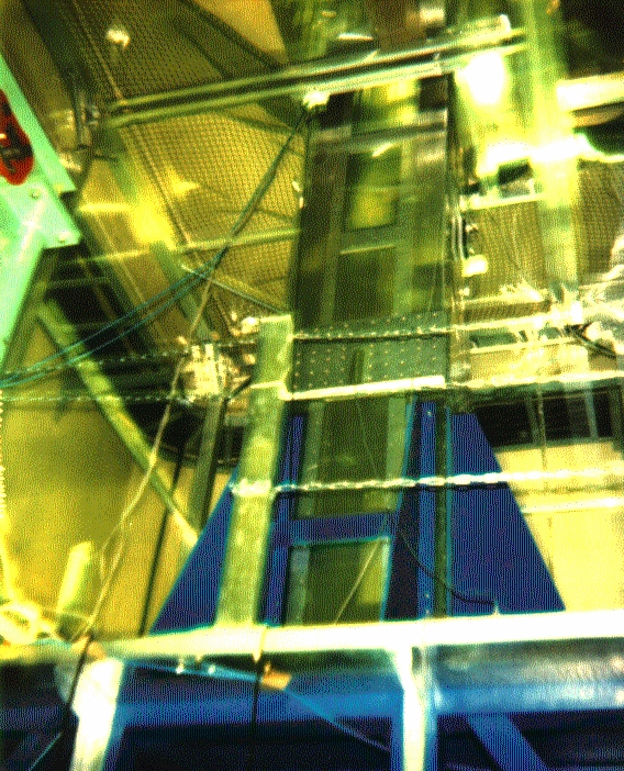
A picture of the test chamber is available below.
 A picture of the 4.6m chamber
The chamber has been built to study the feasibility of a precision
central drift chmber with a large wire length.
The chamber has mini-jet cells
each containing 5 sense wires
made of gold-plated tungsten. The wirers are 30 microns
in diameter and 4.6m in length.
The field wires are, on the other hand, made of aluminium and
have a diameter of 125 microns.
Wire Position Measurement System
The most difficult part of the construction of a long chamber
is the control of wire positions which are subject to
gravitational and electrostatic sags.
We have developed a wire position measuring system which
consits of
two telescopic microscopes,
one for horizontal and one for vertical positions, equipped with
CCD cameras.
 Wire position measurement system
The viewable area has a dimension of about 1mm times 1mm with
a focal depth of about 1mm.
The horizontal and vertical positions of the telescopes are
measured by precision linear scales with a spatial resolution of
a few microns and
the position readings
are electrically logged together with the wire image.
To see a sample image of a wire illuminated by a laser beam,
click here.
Cosmic Ray Tests
Cosmic ray tests have been carried out with a candidate
gas mixtrue (CO2:Iso-Butane=90:10) provided through
a gas mixing system
using mass flow meters. The system is also equipped with
a O2 monitoring system.
Two scintillation counters sandwich the 4.6m chamber and
their coincidence signals a cosmic ray passage, thereby
triggering the data taking system (see
this for our setup).
The positions of the two scintillation counters are
moved to study incident angle dependence (see
this for instance).
Sense wire signals are sent to 8-bit FADC's driven at
500 MHz through charge sensitive pre-amplifiers.
Typical chamber signals look like
this.
Preliminary Results
 Back to JLC CDC Home Page
kurihara@jlcux1.kek.jp Mar 14, 1994
Back to JLC CDC Home Page
kurihara@jlcux1.kek.jp Mar 14, 1994
 A picture of the 4.6m chamber
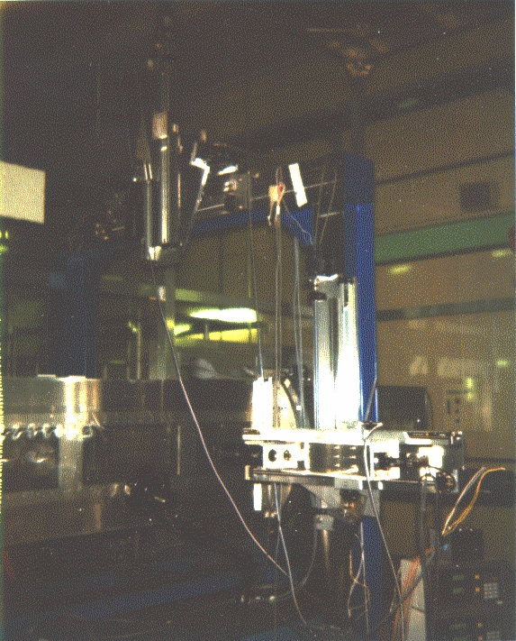 Wire position measurement system