
The JLC ATF group is charged of R&D aiming at a possible design of the JLC Accelerator with the center-of-mass energy of 300-500 GeV. Here in this home page we introduce you to activities of the ATF group. The home page is still incomplete but to be enriched gradually. Any comments or suggestions are welcome and to be directed to takeda@jlcux1.kek.jp
 What's New?
ATF Group Member
Current Activities
1.54 GeV ATF
Injector Linac
Getting
Started
ATF Group Calendar
Library
What's New?
Introduction of the ATF Group
Current Activities
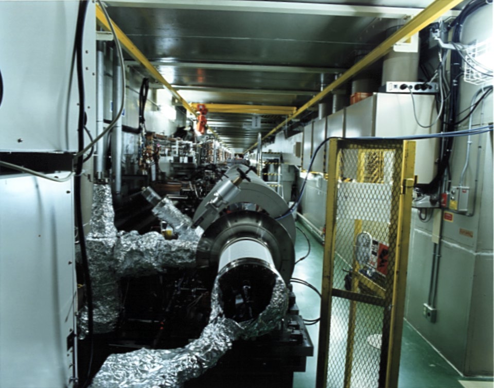
Introduction of the 1.54 GeV ATF Injector Linac
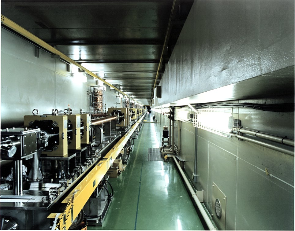
The 1.54 GeV S-band Linac
The injector consists of a conventional thermionic gun, a 357 MHz
subharmonic buncher, and a 3 m long S-band buncher structure which is
followed by 3 m long constant gradient traveling wave structures. The overall
length of the linac is 75 m in which 18 structures, focusing magnets, and
various monitors are placed.
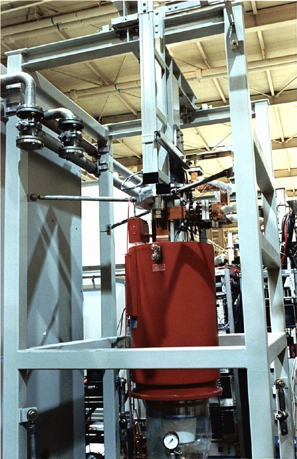
The 100 MW S-band Klystron
Two structures are driven by one 100 MW klystron which can produce 4.5
micro-sec long RF pulse.
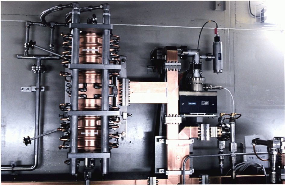
The 400 MW SLED Cavity
A newly developed SLED cavity compresses the output pulse from the klystron
and produces a 1 micro-sec long RF pulse with a peak power of 400 MW. The
compressed pulse is divided into two and fed to each structure providing an
average acceleration gradient of 40 MeV/m with beam loading. In the present
design two of the 18 structures are operated with slightly different
frequencies, which compensates the energy differences and keeps the
bunch-to-bunch energy spread to about 0.15%. The invariant emittance at the
entrance of the regular section is expected to be 3 x 10**-4 rad.m. The
emittance blow-up in the injector is required to be less than 50 % in order
to match the ring acceptance. The lattice was designed to meet this
requirement with a minimum space factor. Two triplets are only placed at the
upstream end and doublets are limited to the first half of the linac. The
remaining half of the linac simply consists of singlets. The alignment
tolerance is 200 microns for both structures and quads, which is expected to
be achievable using a wire alignment method.
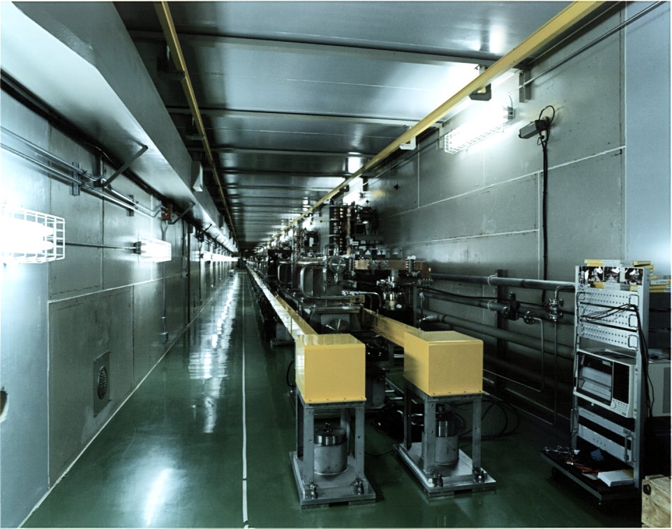
The Wire Alignment System
Needless to say, it is essential that a multi-bunch beam can be extracted
with sufficient intensity from the thermionic gun. To this end we have been
developing a grid driver which consists of a fast ECL circuit and an RF power
amplifier.
The Electron Source
Recently the thermionic electron source is succeeded in producing 20
buncheswith 2.8 nsec bunch spacing. The intensity of each bunch was measured
to be 3 x 10**10 particles, which is required for the damping ring.
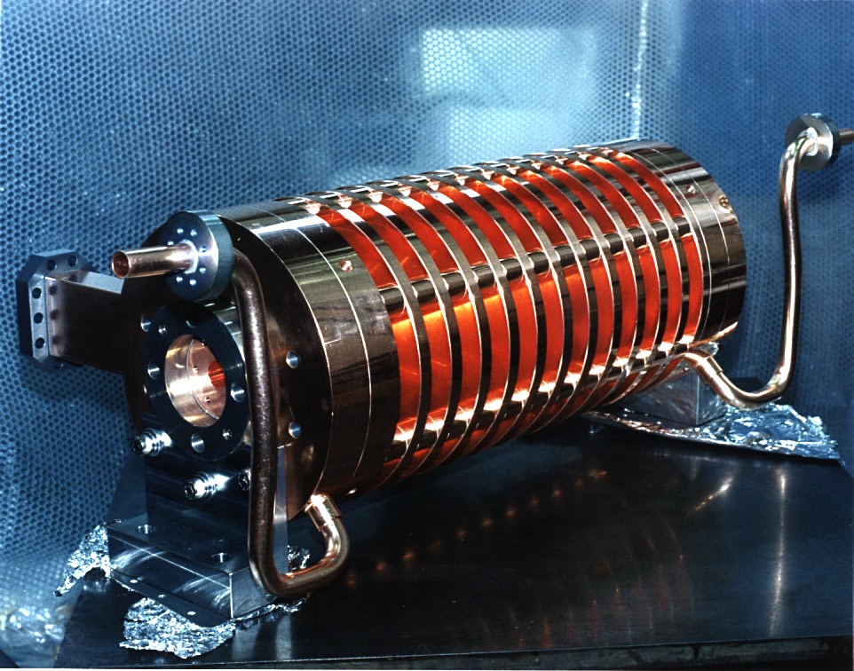
The Choke Mode Cavity
The choke mode cavity damps the higher order modes generaed by the
bunch-cavity intaraction. The multi-bunch beam has been accelerated by the
accelerating gradient of 52 MeV/m in the choke mode cavity.
Getting Started
ATF group Calendar
Library
 Back to ATF Home Page
Back to JLC Home Page
_____________________________________________________________________________
_____________
_____________
Back to ATF Home Page
Back to JLC Home Page
_____________________________________________________________________________
_____________
_____________